
INtime SDK Help
Chronos PTP States and Servo
Precision Time Protocol (PTP), defined in IEEE 1588, enables clocks distributed across a network to synchronize with a selected reference clock. To achieve this, participating devices exchange PTP messages and use their timestamps to determine the time difference between the reference and the local clock. This information provides the basis for correcting the local clock and maintaining synchronization during operation.
Within Chronos, synchronization involves two separate functional components. The PTP protocol engine handles communication with other PTP devices, master selection, and the operational state of each PTP port. The servo processes the available timing measurements and requests adjustments to the local clock. Although these components work together, each maintains its own state machine and serves a different purpose.
| Component | Responsibility |
|---|---|
| PTP protocol engine | Discovers and selects a master, exchanges timing messages, and maintains the PTP port state. |
| Clock measurement path | Derives timing information, including the offset from the selected master. |
| Chronos servo | Tracks its own convergence state and requests time or frequency adjustments. |
| Local PTP clock | Applies supported adjustments to its time and/or rate. |
The PTP port state describes a port's role in the network, while the servo state describes the progress of local clock adjustment. These states must be evaluated independently.
For example, a port can already be in SLAVE state and receive timing information while the servo is still correcting the clock offset or rate. The servo may also leave fine synchronization without the PTP port changing state. Therefore, SLAVE alone does not guarantee the desired clock accuracy. The servo state and calibration indication provide additional information about convergence, but do not replace a direct accuracy measurement.
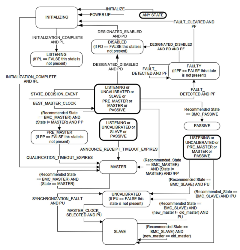
IEEE 1588-2019 defines the following states for stateful PTP ports. The state identifies the protocol behavior of a port, not the current magnitude of its clock offset.
| Port state | Meaning |
|---|---|
| INITIALIZING | The port is being initialized before normal protocol operation. |
| FAULTY | A detected fault prevents normal operation. |
| DISABLED | The port is administratively or operationally disabled. |
| LISTENING | The port observes Announce information while determining the appropriate role. |
| PRE_MASTER | The port is preparing to operate as master. |
| MASTER | The port serves timing information as a master. |
| PASSIVE | The port does not act as the selected slave or master on this link. |
| UNCALIBRATED | The port has a selected master but has not yet completed the required transition into SLAVE operation. |
| SLAVE | The port follows the selected master using the applicable synchronization mechanism. |
The PTP state machine responds to initialization, enable/disable controls, detected faults, timeout events, and state-decision results. The recommended port state is influenced by master selection. IEEE 1588 defines variants and exceptions for different port and instance configurations; the outline below is intentionally simplified.
A state transition is not necessarily caused by a single received timing message. In many cases, the port evaluates information collected over time, including Announce messages and the outcome of the master-selection process. This distinction is important when diagnosing why a port changes from a slave-related state to a master-related or listening state.
| Trigger / situation | Typical state progression |
|---|---|
| Power-up | INITIALIZING → LISTENING (when initialization completes and operation is enabled) |
| A superior master is selected | LISTENING / other eligible state → UNCALIBRATED → SLAVE |
| Local clock is selected to provide time | Eligible state → PRE_MASTER → MASTER (where qualification is required) |
| Announce receipt timeout / role reevaluation | State-decision process may select a different role |
| Fault detected | Applicable operational state → FAULTY |
| Port disabled | Applicable state → DISABLED |
INITIALIZATION_COMPLETE ends initialization. STATE_DECISION_EVENT causes the port role to be reconsidered. MASTER_CLOCK_SELECTED supports entry into the slave role. ANNOUNCE_RECEIPT_TIMEOUT_EXPIRES can trigger reevaluation when expected master information is no longer received. SYNCHRONIZATION_FAULT can affect slave operation.
In particular, UNCALIBRATED and SLAVE are protocol states. The application must not equate a transition into SLAVE with proof of a specified synchronization error bound.
For diagnostics, the port state should be considered together with the selected master, message reception, and the measured clock offset. A stable SLAVE state indicates that the port has the slave protocol role, while the separate servo status indicates whether the local clock has reached the application-defined synchronization condition.
The Chronos servo is responsible for calculating adjustments intended to bring the local clock into alignment with the selected master. Its interface accepts timestamps and computed PTP values and produces a clock-period adjustment and, when needed, a clock-time adjustment. The servo state is independent of the PTP port state.
| Servo state | Explanation |
|---|---|
| Init | Initialize or restart servo operation. |
| Jump | Correct a substantial clock-time difference. |
| Wait | Allow measurements to settle after time adjustment. |
| Synt | Bring the local clock rate closer to the reference. |
| Sync | Maintain fine synchronization of the local clock. |
The implemented default servo follows this primary progression:
INIT → JUMP → WAIT → SYNT → SYNC
The WAIT state lasts for a settling period. SYNT continues until recent offsets satisfy the configured acceptance condition, then enters SYNC. If that condition is no longer satisfied in SYNC, the servo returns to SYNT. If SYNT does not converge within its retry window, the servo may return to JUMP.
| Current state | Transition condition | Next state |
|---|---|---|
| Init | Next state-machine execution | Jump |
| Jump | Time correction has been requested | Wait |
| Wait | Settling cycles completed | Synt |
| Synt | Recent offsets within accepted range | Sync |
| Synt | Retry interval reached without convergence | Jump |
| Sync | Recent offsets outside accepted range | Synt |
The state machine is evaluated when the servo calculation runs; the transitions above do not imply fixed wall-clock durations.
Jump and Wait indicate that the servo is not yet in normal fine synchronization. Synt indicates active convergence toward an acceptable offset history. Sync indicates that the configured offset-history acceptance condition has been met. A return from Sync to Synt indicates that the acceptance condition was no longer satisfied.
The following configuration items influence observable state progression. Values are the defaults expressed by the supplied implementation; they are not universal IEEE 1588 requirements.
| Parameter | Default | Purpose |
|---|---|---|
| OffsetLimitForSync | 10.000 ns | Accepted absolute offset limit for synchronization. |
| OffsetsInRangeForSync | 3 | Number of recent offsets required within the limit. |
| SettleAfterJump | 3 cycles | Intended settling duration after a time correction. |
| WaitBeforeNextJump | 10 cycles | Retry interval before another time correction. |
| AbsToRelJumpLimit | 1.000.000.000 ns | Selects the category of clock-time correction. |
Implementation note: the supplied state-machine code uses a fixed settling-cycle constant in the WAIT transition. The effective relationship between that constant and the configurable SettleAfterJump value should be verified before relying on nondefault settings.
The interface also permits configuration of the servo controllers. Their coefficients, formulas, internal limiting logic, and tuning strategy are outside the scope of this document.
The servo uses different clock adjustments during convergence: a correction of the current clock time (Jump), an adjustment of the rate at which the hardware clock advances (Synt), and fine correction while synchronized (Sync). These operations address different aspects of the difference between the local clock and the master.
Clock time adjustment (Jump) A time jump corrects the existing difference between the local clock and the master. The default Chronos servo distinguishes between large and small corrections using AbsToRelJumpLimit. For an offset above this threshold, the clock can be set to an absolute time. This changes the clock value directly and is suitable for large initial discrepancies. For smaller offsets, suitable hardware may support a relative adjustment distributed over several hardware clock cycles. Rather than replacing the current timestamp immediately, the hardware temporarily modifies the amount added on each tick until the requested correction has been applied. This can maintain monotonically advancing clock time and avoid a sudden timestamp discontinuity. For example, the Intel I210 supports this type of gradual correction through its TIMADJ register.
Clock frequency adjustment (Synt) Even after the current time has been corrected, the local oscillator may run slightly faster or slower than the master. Syntonization addresses this ongoing rate difference. Instead of changing the clock to a particular timestamp, the hardware clock increment is adjusted so that its time advances at approximately the same rate as the reference. On a hardware clock, frequency adjustment is typically performed by changing the increment applied on each clock tick. Unlike a finite time correction, a modified increment continuously changes how quickly the clock advances. Chronos uses this distinction to separate the initial time alignment from ongoing rate alignment.
Fine synchronization (Sync) Once the recent measured offsets remain within the configured synchronization range, the servo enters Sync. At this stage, the clock is already close to the master in both time and rate. The objective is to keep the remaining time offset small while compensating for minor drift and changes in the measured offset. In practical hardware, fine synchronization generally uses small rate adjustments rather than repeatedly setting the clock to a new absolute timestamp. Such adjustments slightly change how quickly the hardware clock advances, allowing the remaining offset to be reduced over time while maintaining continuous clock operation. The exact correction applied depends on the clock hardware and the servo implementation. Sync is not a permanent lock: if the recent offsets no longer satisfy the configured acceptance condition, the default servo returns to Synt to re-establish convergence. The Sync state therefore indicates that the servo currently meets its software acceptance condition, not a guaranteed absolute accuracy.
The description above explains the hardware mechanisms and their observable effect. It intentionally does not specify the proprietary algorithm used to calculate the requested corrections.
The PTP protocol engine determines the port role and provides timing measurements. The servo uses those measurements to drive the local clock toward the reference. Their state names should not be interpreted as interchangeable.
| PTP state | Servo state | Interpretation |
|---|---|---|
| LISTENING | Any / not yet active | The port has not established its operating role; valid servo convergence cannot be assumed. |
| UNCALIBRATED | Init / Jump / Wait / Synt | The protocol is preparing for slave operation while the clock may still require convergence. |
| SLAVE | Sync | The port is following a master and the default servo reports calibrated. |
| MASTER | Not inferred | The port serves as master; the default slave-oriented servo state cannot be inferred from this role alone. |
| Scenario | Expected high-level behavior |
|---|---|
| Startup | PTP initializes and determines a role. Once usable timing measurements are supplied, the servo can progress from Init toward Sync. |
| Initial large offset | The servo can request a clock-time correction, then allow measurements to settle before convergence. |
| Normal synchronized operation | The port may remain SLAVE while the servo remains Sync, provided its acceptance condition continues to hold. |
| Offset exceeds acceptance condition | The servo returns from Sync to Synt even if the PTP port role does not change. |
| Master loss or master change | The PTP protocol reevaluates the selected master and port role. The exact Chronos servo reset/recovery path requires integration-code verification. |