
INtime SDK Help
USB
Universal Serial Bus (USB) is a serial bus standard for connecting one or more devices to a single host computer. The hardware connection at the host is controlled by a Host Controller Interface (HCI). The physical connection is a serial link which transmits data at a raw rate of 12 Mbps (for USB 1.1), 480 Mbps (USB 2.0), 2 Gbps (USB 3.0). The design is such that devices may be added or removed from the bus while the system is live. Power for the devices may also be delivered via the bus, or devices may have their own power supply.
On INtime for Windows, USB is not enabled by default. To enable USB, first assign the required HCI devices to INtime using the INtime Device Manager. Enable the stack by checking the "Enable" option in the Auto Load tab of the node configuration utility in the INtime Configuration. After rebooting and starting the node, the software will start and install a driver for each controller assigned to that node.
On INtime Distributed RTOS, USB is enabled by default on the first node
The USB interconnect supports data traffic between a host and a USB device. The basic flow and interrelationships of the USB communications model are shown in the next figure.
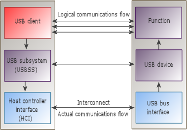
The host and the device are divided into the layers depicted in the previous figure. The corresponding interfaces on the device are implementation-specific. All communications between the host and device ultimately occur on the physical USB wire, but there are logical host-device interfaces between each horizontal layer.
The previous figure illustrates the host's view of its communications with the device.
There is only one host per USB. The software components of the host include:
The USBSS process loads the system USB services and also the drivers for UHCI, OHCI, ECHI and XHCI interfaces, as well as the standard HUB driver. A USB client is any process that uses USB services.
There are a wide range of USB devices intended for a variety of purposes, and this means that implementation details can vary widely.
A device can be self powered, bus powered, or both. The USB can provide a power supply up to 500mA for its devices. If only bus powered devices exist on the bus, the maximum power dissipation could be exceeded and therefore self powered devices exist. They need to have their own power supply. Devices that support both power types can switch to self-powered mode when attaching an external power supply.
Even the maximum communication speed can differ for particular USB devices. The USB specification differentiates between low- and full-speed devices. Low-speed devices (such as mice, keyboards, joysticks, etc.) communicate at 1.5Mbps and have only limited capabilities. Full-speed devices (such as audio and video systems) can use up to 90% of the 12Mbps which is about 10Mbps including the protocol overhead.
Physically, a computer's rear panel can contain one, two or four USB ports, which can be used to attach normal devices or a hub. The maximum number of user devices is reduced by the number of hubs on the bus (i.e. if you attach 50 hubs, then at most 77 (=127-50) additional devices can be attached. Hubs are always full-speed devices. If the hub is self powered, then any device can be attached to it. However if the hub is bus powered, then only low-power (100mA max) devices can attach to it. A bus-powered hub should not connect to another bus powered hub; you should alternate between bus- and self-powered hubs.
Normally, a virtual root hub handles the host controllers physical ports. This hub is simulated by the host controller's device driver and helps unify the bus topology. This allows the USB subsystem's hub driver to handle every port in the same way.
USB communication is bi-directional and uses four different transfer types. Data directed from the host to a device is called downstream or OUT transfer. The other direction is called upstream or IN transfer. Different transfer variants are used, depending on the device type:
When a USB device attaches to the bus, the USB subsystem enumerates it, i.e assigns a unique device number (from 1 to 127), and then reads the device descriptor.
The descriptor is a data structure which contains information about the device and its properties. The USB standard defines a hierarchy of descriptors.
The standard device and interface descriptors contain fields that are related to classification: class, sub-class, and protocol. A host system can use these fields to associate a device or interface to a driver, depending on how they are specified by the class specification. The USB Device Working Group defines valid values for the device's class fields and interface descriptors.
Grouping devices or interfaces together in classes, then specifying the characteristics in a Class Specification allows the development of host software which can manage multiple implementations based on that class. Such host software adapts its operation to a specific device or interface using descriptive information presented by the device. A class specification serves as a framework that defines the minimum operation of all devices or interfaces which identify themselves as members of the class.
A USB Client is an application that uses USB services to access the functionality of one or more USB devices. A client may be a device driver for a given USB device, or any other application which needs access to the USB. A client interacts with the USB Subsystem via the USB API and must perform certain actions to access USB devices.
All USB calls are referenced by the usbif3.h header file. Include this file whenever you want to make a USB client. To access the USB subsystem functions, USB clients should be linked with the usbif.lib file.
A USB client must register itself with the USB subsystem. To do this, the client must register attach and detach functions with the stack.
This example shows a typical initialization sequence in a USB client. It is taken from the USB keyboard sample project.
| Client initialization |
Copy Code
|
|---|---|
|
void main(void) |
|
The first callback function is the attach function, called when the client first registers with the USB subsystem, or when a new device is inserted in the USB. It is called for each device and each interface on the USB not yet registered with a client. The function must determine whether this client is interested in the interface presented to it. It does that by returning a non-zero integer value from the function.
This example illustrates how to use a match function. Taken from the USB keyboard sample project, this case looks for an interface of the Human Interface Class with a single input interrupt endpoint.
| attach function |
Copy Code
|
|---|---|
|
static int32_t kbd_attach(struct usbDeviceInfo * udi) return 0; |
|
More complex matching may use the UsbMatchId call, which allows a device or interface descriptor to be matched against a list of criteria such as device and vendor IDs, version number, class, subclass, and protocol IDs for both device and interface descriptors.
This function is called after the client returns a non-null context value from its match function. The USB subsystem creates a device handle for the device or interface, then calls this function. This function validates the device or interface just matched and initializes it. The context value originally returned from the match function is passed to this function. This function also returns a valid context pointer on success; if it fails it should return NULL.
The USB sample project includes an example of how to perform interface validation. The interface validation might look similar to this:
    // Validate the interface:
        //   keyboard should have one endpoint, check the direction and type
    if (UsbGetInterfaceDescriptor(dev, &iface) != 0)
                return NULL;
        if (iface.bNumEndpoints != 1)
                return NULL;
    if (UsbGetEndpointDescriptor(dev, 0, &endpoint) != 0)
                return NULL;
        if ((endpoint.bEndpointAddress & USB_ENDPOINT_DIR_MASK) == USB_DIR_OUT)
                return NULL;
        if ((endpoint.bmAttributes & USB_ENDPOINT_XFERTYPE_MASK) != USB_ENDPOINT_XFER_INT)
                return NULL;
This function is called either when the client calls UsbCloseDevice, or when the device associated with the client is removed from the bus.
All USB transfers to and from an endpoint are encapsulated in a structure called a USB Request Block ("URB"). After the transfer has been completed the URB may be deallocated or reused for communication with the same endpoint. The endpoint is referred to by its "pipe", a number that uniquely references the endpoint. A series of macros creates pipe values for different endpoints:
USB_MKSNDCtrLPIPE(dev, ep) |
Create an output control pipe for device dev, endpoint ep |
USB_MKRCVCtrLPIPE(dev, ep) |
Create an input control pipe for device dev, endpoint ep |
USB_MKSNDBULKPIPE(dev, ep) |
Create an output bulk pipe for device dev, endpoint ep |
USB_MKRCVBULKPIPE(dev, ep) |
Create an input bulk pipe for device dev, endpoint ep |
USB_MKSNDINTPIPE(dev, ep) |
Create an output interrupt pipe for device dev, endpoint ep |
USB_MKRCVINTPIPE(dev, ep) |
Create an input interrupt pipe for device dev, endpoint ep |
USB_MKSNDISOCPIPE(dev, ep) |
Create an output isochronous pipe for device dev, endpoint ep |
USB_MKRCVISOCPIPE(dev, ep) |
Create an input isochronous pipe for device dev, endpoint ep |
The normal sequence of calls for use with an endpoint is as follows:
| UsbBulkXferAsync | Asynchronously perform a bulk transfer |
| UsbBulkXfer | Synchronously perform a bulk transfer |
| UsbInterruptXferAsync | Asynchronously perform a interrupt transfer |
| UsbInterruptXfer | Synchronously perform a interrupt transfer |
| UsbControlXfer | Perform a control endpoint transfer |
| UsbClearStall | Clear an endpoint stall condition |
| UsbGetEndPointStatus | Get the status of an endpoint. |
| Set up an interrupt transfer |
Copy Code
|
|---|---|
|
// set up an interrupt transfer pipe = USB_MKRCVINTPIPE(dev,endpoint.bEndpointAddress); |
|
When functions return an error, use the number to find the code and its description in this table :
| Code | Identifier | Description |
|---|---|---|
| 0 | USB_ERR_NORMAL_COMPLETION | Normal completion. |
| 1 | USB_ERR_PENDING_REQUESTS | A transfer could not be started because a previous operation is still in progress. |
| 2 | USB_ERR_NOT_STARTED | Operation was not started. |
| 3 | USB_ERR_INVAL | A parameter was invalid. |
| 4 | USB_ERR_NOMEM | No memory available to stack. |
| 5 | USB_ERR_CANCELLED | Operation was canceled. |
| 6 | USB_ERR_BAD_ADDRESS | Device address is invalid. |
| 7 | USB_ERR_BAD_BUFSIZE | Buffer is too small. |
| 8 | USB_ERR_BAD_FLAG | Invalid transfer flag. |
| 9 | USB_ERR_NO_CALLBACK | Internal callback is invalid. |
| 10 | USB_ERR_IN_USE | Device is already in use. |
| 11 | USB_ERR_NO_ADDR | No such USB device. |
| 12 | USB_ERR_NO_PIPE | Pipe is invalid. |
| 13 | USB_ERR_ZERO_NFRAMES | Transfer error, zero frames. |
| 14 | USB_ERR_ZERO_MAXP | Internal buffer size should not be zero. |
| 15 | USB_ERR_SET_ADDR_FAILED | Could not set device address. |
| 16 | USB_ERR_NO_POWER | Insufficient power to device. |
| 17 | USB_ERR_TOO_DEEP | Too many hubs (>5). |
| 18 | USB_ERR_IOERROR | An error occurs during data transfer. |
| 19 | USB_ERR_NOT_CONFIGURED | The device is unconfigued. |
| 20 | USB_ERR_TIMEOUT | A timeout occurred waiting for the device. |
| 21 | USB_ERR_SHORT_XFER | A short data transfer occurred. |
| 22 | USB_ERR_STALLED | The device is stalled. |
| 23 | USB_ERR_INTERRUPTED | An operation was interrupted. |
| 24 | USB_ERR_DMA_LOAD_FAILED | A DMA error occurred. |
| 25 | USB_ERR_BAD_CONTEXT | There is confusion about a devices setup. |
| 26 | USB_ERR_NO_ROOT_HUB | The root hub is missing. |
| 27 | USB_ERR_NO_INTR_THREAD | The interrupt thread is missing. |
| 28 | USB_ERR_NOT_LOCKED | An expected lock is missing. |
| 255 | USB_ERR_NO_STACK | The USB stack is not ready. |
| 256 | USB_ERR_NO_SUCH_CALL | An invalid USB call was attempted. |
| 257 | USB_ERR_NO_DEVICE | USB device handle is no longer valid. |
| 258 | USB_ERR_FAULT | A fault occurs copying to or from user space. |
| 259 | USB_ERR_NOVIRTUAL | No more user virtual memory. |
| 260 | USB_ERR_NOMEMORY | No more user physical memory. |