
INtime SDK Help
Virtual Ethernet Configuration
The INtime Virtual Ethernet system provides a Virtual Ethernet (VEther) connection between INtime node(s) (and Windows on an INtime for Windows system) on a single PC host. It consists of two components; the Windows side driver and the INtime side driver (ven). With INtime Virtual Ethernet:
Note: INtime Virtual Ethernet is not ideal for high-performance networked application. If you need high performance, real-time Network capabilities, it is strongly recommended to assign dedicated network interface adapters to each INtime node and Windows.
Note: While using Virtual Ethernet makes it easier to port an existing application in the above case, using other communication methods, such as shared memory or mailbox, will yield better performance.
No physical hardware is associated with the TenAsys Virtual Ethernet adapter; therefore, we must create "virtual" network MAC addresses. By default a random MAC address is generated when the interface is installed. This avoids problems when the virtual network is exposed to the outside by bridging a virtual adapter and a real Ethernet interface. An alternate scheme based on the node's CPUID is also available (this is the scheme which was used until INtime version 6).
An OUID (Organizationally Unique Identifier) or MAC (Media Access Control) address as defined by the IEEE as a 48-bit value consisting of three octets (bytes) identifying the Ethernet hardware vendor followed by three vendor specific octets.
| Media Access Control OCTET # | |||||
|---|---|---|---|---|---|
| 0 | 1 | 2 | 3 | 4 | 5 |
| XX | XX | XX | XX | XX | XX |
| Organization ID | Vendor Specific ID | ||||
Generally, the vendor specific octets are used to generate 224 unique MAC addresses.
An Ethernet frame is variable in length and contains between 46 and 1500 bytes (octets) of payload data. The format of an Ethernet frame follows (the numbers after each label indicate the number of octets in the field):
| Destination:6 | Source:6 | Type:2 | Data:46-1500 | CRC:4 |
The Destination and Source fields are 48-bit MAC addresses (see the previous section).
The two low-order bits of the first octet of the Destination MAC address have special meaning:Since TenAsys has not been assigned a MAC address Organization ID by the IEEE the Windows virtual Ethernet driver uses a locally administered address. A MAC address with the local flag set in octet[0] is expressed as:
02:00:00:00:00:00
It is possible to use any MAC address for the Virtual Ethernet adapter provided octet[0]:0 equals 0 and octet[0]:1 equals 1, as outlined by the previous section.
For the INtime virtual network, the octets are generated randomly when the interface is installed, but bit 1 of the first octet is always set, and bit 0 is always cleared for the Unicast address associated with the Virtual Ethernet adapter.
For the legacy addressing scheme used until INtime 6, and stil lavailable by configuration, the default MAC address is selected as:
42:00:00:00:00:nn
where the last octet "nn" is the Processor ID number
In this scheme, the first 5 octets ("42:00:00:00:00" in the default case) are common to all INtime nodes and Windows. For Windows, the last octet should be 0xff by default. The INtime nodes, by default, replace the last octet of the MAC address with their Processor ID# at runtime. For example, if the Windows side MAC address is 42:00:00:00:00:ff and the driver is running on a node whose Processor ID# is 3, then the actual MAC address will be 42:00:00:00:00:03.
The default MAC address for Windows side of the Virtual Ethernet is 42:00:00:00:00:ff (see the figure below). The default MAC address does not need to be changed unless the interface is configured as a bridge (see Configuring the Virtual Network as a Bridge). If there are multiple PCs with INtime Virtual Ethernet configured as bridges in you LAN environment, then care must be taken to choose unique MAC addresses to all of these systems. As described above, the last octet, octet[5], of the MAC address will be modified by INtime system at runtime by default. So to assign unique MAC addresses to PCs with Virtual Ethernet, varying octet [4] is recommended to simplify administration.
Windows side MAC address can be configured in "TenAsys Virtual Ethernet Adapter Properties" dialog box. The Windows side of the Virtual Ethernet driver uses the MAC address exactly as specified in the Properties dialog box. Even though it is possible to select any MAC address in the Properties dialog box, it is strongly recommended that the last octet of the Windows side MAC address is left as 0xff (or 255 in decimal, as seen in the Properties dialog). The reason is detailed in the next section.
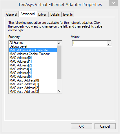
Windows Virtual MAC address
Note: The virtual adapter's property page can be accessed by locating the TenAsys Virtual Ethernet Adapter in the Windows device manager tree.
By default, INtime side MAC addresses are generated automatically on installation of the Virtual Ethernet interface on INtime (INtime for Windows or INtime Distributed RTOS). If, for some reason, you need to change the address of an INtime node, you need to manually configure this. To assign specific MAC addresses to nodes, you need to manually edit "loader.cfg" file for each node. For example, here is the procedure to assign a MAC address "42:11:22:33:44:55" to NodeA:
For INtime Distributed RTOS, locate the loader.cfg file in /config/[nodename]/etc. You will likely need to copy the file offline via FTP to be edited and then reinstall the file.
Create a Virtual Ethernet Device using the INtime configuration tool. Only one such device may be created. The Static IP Configuration may be filled in or, if DHCP is selected, left blank.
INtime network interface address configuration
From Start|Control Panel, open the Network Connections applet and select the connections you wish to bridge.
Windows network bridging setup
Windows network bridging completed.
The bridge may obtain an address automatically or you may configure one yourself.
If during this setup phase you have previously started the INtime kernel and networking you may need to restart the kernel to complete configuration of the bridge.
For our purposes we select two IP addresses from a standard non-routable (private) IP subnet:
Other possible non-routable sub-nets are:
You may of course choose other sub-nets or net-masks as appropriate for your environment.
Set the IP address for the INtime side of the virtual network.
INtime static IP address configuration
Configure the INtime connection from Start|Control Panel|Network Connections and deselect all protocols except TCP/IP.
Modifying TCP/IP properties
Windows static IP address configuration
The TenAsys Virtual Ethernet Adapter will show "Network cable unplugged" until you start the INtime kernel and the INtime networking services.
Network status while INtime Kernel stopped
After you start the INtime kernel the Network Connection status will change to show that the interface is connected and working.
Network status while INtime Kernel running
In this configuration the IP addresses are unknown until we query the interfaces. Since we have configured the Windows interfaces to be bridged, we can use the bridge address. We obtain it with the Windows ipconfig command:

Windows network adapter information
We can determine the INtime interface IP address by running the INtime ifconfig.rta utility on the INtime kernel. In the example below we do this by using the INtime "piperta" command from DOS prompt. The IP address is displayed after "inet", in this example, it is "172.16.0.38".
INtime network Interface information
In this configuration we know the address for the Windows and INtime interfaces; 10.1.1.1 and 10.1.1.2, respectively. We will ping the interfaces at the known IP addresses to verify the configuration.
If you are using Windows XP with Service Pack 2 you must allow the ICMP request from the Windows Security Center from the control panel. Go to the advanced tab, and select the ICMP settings, then check the "Allow incoming echo request". If you have a third party Firewall installed on your machine, you may need to also change its setting to allow the incoming ICMP request.
Allow incoming ICMP request
To ping the interface from Windows use the Windows ping command:
Running Ping From Windows
To ping the interface from the INtime kernel use the ping.rta utility. "-c" option specifies the total ping request counts to be sent.
Running Ping From INtime
It is also possible to create a bridge between two or more adapters on the INtime network stack. You might want to do this, for example, if:
On your INtime node, configure networking with the virtual Ethernet adapter configured, or add a virtual Ethernet adapter to an existing network configuration.
If you wish to configure your nodes using DHCP, make sure this is checked in the NIC configuration for the virtual Ethernet.
If there are multiple INtime nodes which are going to participate in the virtual network, make sure the network is configured on all participating nodes.
Choose the node which will also service the real Ethernet adapter and configure the NIC for this adapter.
On the node where the physical-virtual bridge is to be created, locate the netuser.cfg file in the %INTIMECFG%\[nodename]\etc directory for the node. This works for both INtime for WIndows and for INtime Distributed RTOS. On INtime Distributed RTOS you willneed to copy the file to a host where you can edit it (using a FTP client), then return it afterwards.
Uncomment the following lines in netuser.cfg:
# Create a bridge and add interface ven0 and ie1g0
ifconfig.rta -q bridge create
# Edit this list of adapters to match the ones present on your node
ifconfig.rta bridge0 addm ven0 addm ie1g0 up
# Bring the ven0 interface up explicitly if you do not assign an address to it
ifconfig.rta ven0 up
#
This sequence of commands creates a bridge, then adds interfaces to it. Finally, the ven0 (virtual Ethernet) interface needs to be brought up if it is being configured via DHCP.